Hammer Strength

Heavy Duty Elite iD Racks

Strength Systems

Owner's Manual

ELT-HR, ELT-PR, ELT-HHCR, ELT-PHCR, ELT-PPCR

1022942-0001 AE

Cover Image

i Corporate Headquarters

  • Columbia Centre III, 9525 Bryn Mawr Avenue, Rosemont, IL 60018 • U.S.A.
  • 847.288.3300 • FAX: 847.288.3703
  • Service phone number: 800.351.3737 (toll-free within U.S.A., Canada)
  • Global Website: www.lifefitness.com
International Offices

AMERICAS

North America

Life Fitness, LLC

EUROPE, MIDDLE EAST, and AFRICA (EMEA)

Belgium, Netherlands, and Luxemburg

Life Fitness (Atlantic) B.V.

All Other EMEA Countries and Distributor Business EMEA*

Life Fitness (Atlantic) B.V.

Brazil

Life Fitness Brasil

United Kingdom

Life Fitness UK LTD

ASIA PACIFIC (AP)

Japan

Life Fitness Japan, Ltd

Latin America and Caribbean*

Life Fitness, LLC

Germany, Austria, and Switzerland

Life Fitness Europe GMBH

Hong Kong

Life Fitness Asia Pacific LTD


Spain

Life Fitness IBERIA

All Other Asia Pacific countries and distributor business Asia Pacific*

Life Fitness Asia Pacific LTD

*Also check www.lifefitness.com for local representation or distributor/dealer

ii User and Service Documents Link

https://lfn.fit/KnowledgeBase

https://lfn.fit/PartStore

Additional information is available online using the links above.

English

.تتوفر معلومات إضافية على الإنترنت باستخدام الرابط أعلاه

Arabic, Saudi Arabia, Primary

点击上面的链接可在线获取更多信息。

Chinese, Simplified, Primary

Flere oplysninger er tilgængelige online gennem linket ovenfor.

Danish

Bijkomende informatie is online beschikbaar via bovenstaande link.

Dutch

Vous trouverez plus d'informations en ligne à l'aide du lien ci-dessus.

French

Zusätzliche Informationen finden Sie online über den oben angegebenen Link.

German

Ulteriori informazioni sono disponibili online utilizzando il link sopra riportato.

Italian

追加情報は上記リンクを使用してオンラインで利用可能です。

Japanese

상기 링크를 통해 온라인에서 추가 정보를 볼 수 있습니다.

Korean

Informações adicionais estão disponíveis on-line, através do link acima.

Portuguese, Brazil, Primary

Дополнительная информация доступна в интернете по ссылке, указанной выше.

Russian

Mediante el enlace anterior podrá acceder a información adicional en línea.

Spanish

Ytterligare information finns online genom att använda länken ovan.

Swedish

İnternet üzerinden daha fazla bilgi edinmek için yukarıdaki bağlantıyı kullanabilirsiniz.

Turkish

.هناك معلومات إضافية متاحة على الإنترنت باستخدام الرابط أعلاه

Arabic,Standard, Secondary

Informazio osagarria eskuragarri dago goiko estekaren bidez.

Basque

Допълнителна информация можете да намерите онлайн, като използвате връзката по-горе.

Bulgarian

Mitjançant l'enllaç anterior podreu accedir a informació addicional en línia.

Catalan

使用上面的連結線上提供額外資訊。

Chinese, Traditional, Secondary

Dodatne informacije možete pronaći na internetu sljedeći vezu iznad.

Croatian

ከላይ የተቀመጠውን አገናኝ(ሊንክ) በመጠቀም መረጃዎች ኦንላይን ያገኛሉ፡፡

Ethiopian

Lisätietoja on saatavissa verkosta käyttämällä yllä olevaa linkkiä.

Finnish

Wubetumi anya nsɛm afoforo aka ho wɔ wɛbsait so denam asɛm a ɛwɔ atifi hɔ a wubemia so so.

Ghana

Πρόσθετες πληροφορίες είναι διαθέσιμες ονλάιν χρησιμοποιώντας το σύνδεσμο παραπάνω.

Greek

.מידע נוסף אפשר לקבל באינטרנט באמצעות הקישור לעיל

Hebrew

További információ elérhető online, a fenti hivatkozás segítségével.

Hungarian

Viðbótarupplýsingar eru fáanlegar á netinu með því að smella á tengilinn hér fyrir ofan.

Icelandic

Plus indicium per superum situm potes invenire.

Latin

മുകളിലുള്ള ലിങ്ക് ഉപയോഗിച്ച് ഓൺലൈനിൽ കൂടുതല് വിവരങ്ങൾ ലഭ്യമാണ്.

Malayalam

Ytterligere informasjon er tilgjengelig på nettet via linken ovenfor.

Norwegian Nyorsk

Dodatkowe informacje są dostępne online pod powyższym odnośnikiem.

Polish

Informações adicionais estão disponíveis online a usar o link acima.

Portuguese, Portugal, Secondary

Informații suplimentare sunt disponibile online, utilizând link-ul de mai sus.

Romanian

Dodatne informacije dostupne su na mreži putem gornjeg linka.

Serbian

Ďalšie informácie sú dostupné online na vyššie uvedenom odkaze.

Slovak

TradeMarkList Gym Wipes, PureGreen 24

Life Fitness® is a registered trademark.

Gym Wipes® is a registered trademark of the 2XL Corporation. PureGreen 24 is a trademark of Pure Green.

Chapter 1: Safety

1.1: Safety Information

It is the sole responsibility of the purchaser of Life Fitness products to read the owner’s manual and warning labels and instruct all individuals, whether they are the end user or supervising personnel, on proper usage of the equipment.

UNDERSTANDING EACH AND EVERY WARNING TO THE FULLEST IS IMPORTANT. IF ANY OF THESE WARNINGS ARE UNCLEAR, CONTACT Life Fitness CUSTOMER SERVICE IMMEDIATELY AT 1-800-351-3737.

This equipment is categorized as class S per EN ISO 20957-1. As such this equipment is only intended for commercial, institutional and/or studio facilities. It is not intended for home use. Contact Life Fitness with any questions regarding this classification.

It is recommended that all users of Life Fitness exercise equipment be informed of the following information prior to use.

Operating Warnings
Warning: This product can expose you to chemicals including 1,3 Butadiene, which is known to the State of California to cause cancer and birth defects or other reproductive harm. For more information go to http://www.P65Warnings.ca.gov
  • Life Fitness does not warrant nor guarantee that component parts used in the manufacture of products offered under the Life Fitness brand are latex-free. Users of these products must take all necessary precautions to prevent accidental contact that could lead to an adverse latex reaction.
  • It is the purchaser’s sole responsibility to properly instruct its end users and supervising personnel as to the proper operating procedures of all equipment.
  • This equipment is not intended for use by children. Keep children under the age of 14 away from the machine.
  • Do not allow users to wear loose fitting clothing or jewelry while using equipment. It is also recommended to have users secure long hair back and up to avoid contact with moving parts.
  • All bystanders must stay clear of all users, moving parts and attached accessories and components while machine is in operation.
Access Control
  • Life Fitness recommends that all commercial fitness equipment be used in a supervised area. It is recommended that the equipment be located in an access controlled area. Control is the responsibility of the facility owner.
Installation
  • Life Fitness requires that all equipment be secured to a solid, level surface to stabilize it and eliminate rocking or tipping over. This must be performed by a licensed contractor. See Bolt to Floor Guide for installation procedure.
  • Life Fitness requires that all Athletic Racks be secured to the floor when used with body weight strap training devices to stabilize and eliminate rocking or tripping over. If necessary, please contact Customer Support Services for any questions.
Proper Usage
  • Do not use any equipment in any way other than as designed or intended by the manufacturer. It is imperative that Life Fitness equipment is used properly to avoid injury.
  • Injuries may result if exercising improperly or excessively. It is recommended that all individuals consult a physician prior to commencing an exercise program. If at any time during exercise you feel faint, dizzy or experience pain, STOP EXERCISING and consult your physician.
  • Keep body parts (hands, feet, hair, etc.), clothing and jewelry away from moving parts to avoid injury.
Inspection
  • Before use, examine all accessories approved for use with the Life Fitness equipment for damage or wear.
  • DO NOT attempt to use or repair any accessory approved for use with the equipment which appears to be damaged or worn.
  • DO NOT use or permit use of any equipment that is damaged and/or has worn or broken parts. For all Life Fitness equipment, use only replacement parts supplied by Life Fitness .
  • Maintain labels, name plates and instructional placards. Do not remove labels or instructional placards for any reason. They contain important information. Contact Customer Support to replace any worn, damaged, or unreadable labels or instructional placards and to ensure that you are always using the latest version of labels and instructional placards.
  • Equipment Maintenance - Preventative maintenance is the key to smooth operating equipment as well as to keep your liability to a minimum. Equipment needs to be inspected at regular intervals.
  • Ensure that any person(s) making adjustments or performing maintenance or repair of any kind is qualified to do so. Life Fitness will provide service and maintenance training at our corporate facility upon request or in the field if proper arrangements are made.
Plate Loaded, Free Weight, and Body Weight Systems
  • If the unit is equipped with weight rods, use only Olympic style weight plates (2.0” bore) for training weight. Do not use dumbbells or any means other than those stated to increase weight resistance - See machine specific section for more information.
  • Always utilize weight plate retention devices such as straps, clamps or pins.
  • Only add weight plates up to the load limits of the unit. Make sure all weight plates are completely placed on the weight rod.
  • Never exceed the load rating for any plate loaded station, body weight station, bench or other free weight device; including specific weight rod and band peg limits. See machine specifications for load limit information.
  • Contact a Life Fitness representative with any questions regarding proper weights and loading.
Warnings and Cautions
  • Warning labels indicate a potentially hazardous situation that could result in serious injury or death if the precautions are not observed.
  • Caution labels indicate a potentially hazardous situation that could result in serious injury or damage to machine if the precautions are not observed.
  • Contact Customer Support Services to replace any worn, damaged, or unreadable labels and to ensure that you are always using the latest version of labels.

1.2: Product Labels

Installers to verify that all labels are accounted for. Replace any labels that are missing or damaged.

General Warning

Serial Number

QR Code

Bar Catch Height

1.3: Label Locations

1.3.1: Half Rack (ELT-HR)

Item Description Qty.
1 General Warning 1
2 Serial Number 1
3 QR Code 1
4 Bar Catch Height 1

1.3.2: Power Rack (ELT-PR)

Item Description Qty.
1 General Warning 1
2 Serial Number 1
3 QR Code 1
4 Bar Catch Height 1

1.3.3: Combo Rack (ELT-HHCR, ELT-PHCR, ELT-PPCR)

Item Description Qty.
1 General Warning 2
2 Serial Number 2
3 QR Code 2
4 Bar Catch Height 2

Chapter 2: Assembly

2.1: Introduction

The Installer must consult the Facility Owner prior to assembly for determining the following:

  1. Required Facility layout and live area
  2. Which way exercisers will be entering the product (ex. power lifting or free weight bench) for proper label placement
  3. Weight horn placement based on available weight plates. See Install Weight Horns and Weight Plate Storage topics for more details.

2.2: Tools Required

  • 3/4” wrench (x2)
  • Torque wrench
  • 7 mm Allen wrench
  • 17 mm wrench

2.3: Component and Hardware List

Front Crossmembers
Item Description
1 3-Handle Bar
2 Straight Bar
3 Rotating Chin
4 3x3
5 3x3 with Arc Bar
6 3x3 with Ball Grips
7 3x3 with Neutral Grips
8 Perch
9 Ballistic Wing
Rear Crossmembers
Item Description
1 Super Duty
2 Super Duty with Sign
Storage Crossmembers
Item Description Length
1 Top Storage Weldment 15in/38cm
2 21in/53cm
3 34.5in/88cm
4 42in/107cm
5 Bottom Storage Weldment 15in/38cm
6 21in/53cm
7 34.5in/88cm
8 42in/107cm
Bar Catches and Supports
    Note:
  • Bar catches and bar supports are sold in pairs.
  • All bar catches should always be used at or above 28" (71 cm) when performing squat exercises.
  • If using HR Bar Catches on the outside of Power Rack uprights, rack is required to be bolted to floor unless it has stability feet.
Item Description
1 4x3 Bar Support
2 HR Bar Catch
3 PR Bar Catch (30.9in/78.4cm wear cover length)
4 PR Bar Catch XL (38.4in/97.5cm wear cover length)
5 PR Flexible Bar Catch (35.4in/89.9cm strap length)
6 PR Flexible Bar Catch XL (47.4in/120.3cm strap length)
Hardware Kit
Item Description
1 Bolt, 1/2" x 4"
2 Bolt, 1/2" x 5 1/2"
3 Bolt, 1/2"-13 x 1.25"
4 Lock Washer, 1/2"
5 Backing Washer
6 Lock Nut, 1/2" Thin
7 Lock Nut, 1/2"
8 Rectangle Tubing Nut, 11GA, 3"
9 Rectangle Tubing Nut, 7GA, 3"
10 Rectangle Tubing Nut, 7GA, 4"
11 Spacer

2.4: Half Rack (ELT-HR)

Note: Half Rack not required to be bolted to floor due to Stability Feet.

2.5: Assembly Procedure

Three or more people will be required for this procedure.

Tip: Read and understand all instructions thoroughly before assembling this unit. Check all items carefully. If there is damage, see the Customer Service section of this manual for proper procedure to return, replace, or reorder parts.

2.5.1: Assemble Uprights and Crossmembers

  1. Lay components out on the ground.
    • The Hammer Strength HS cut-out on the training uprights face out when the rack is assembled.
    • Review the Label Locations topic to make sure that the serial number and warning labels etc. are in the appropriate location for each upright when assembling.
    Item Description Qty.
    1 Storage Upright 1
    2 Training Upright 1
  2. Install bolts, washers, and rectangle tubing nuts securing upper side crossmember to tops of training upright and storage upright using a 3/4" wrench.
    Important: Upper side crossmembers only have holes in the sides and Hammer Lock slots on top.
    Item Description Qty.
    1 Upper Side Crossmember 1
    2 Bolt, 1/2"-13 x 1.25" 4
    3 Lock Washer, 1/2" 4
    4 Rectangle Tubing Nut, 11GA, 3" 4
    5 Rectangle Tubing Nut, 7GA, 3" 2
    6 Rectangle Tubing Nut, 7GA, 4" 2

    Hand tighten hardware.

    Note: Removing end caps at tops of storage and training uprights will help give access to Hammer Locks inside tube. Use a screwdriver to push end caps out from upright tube. Press end caps back into upright tube after bolts are installed.
  3. Install bolts, washers, and rectangle tubing nuts securing lower side crossmember to bottoms of training upright and storage upright using a 3/4" wrench.
    Important: Lower side crossmembers have holes in all four sides.
    Item Description Qty.
    1 Lower Side Crossmember 1
    2 Bolt, 1/2"-13 x 1.25" 3
    3 Lock Washer, 1/2" 3
    4 Rectangle Tubing Nut, 11GA, 3" 2
    5 Rectangle Tubing Nut, 7GA, 3" 1

    Hand tighten hardware.

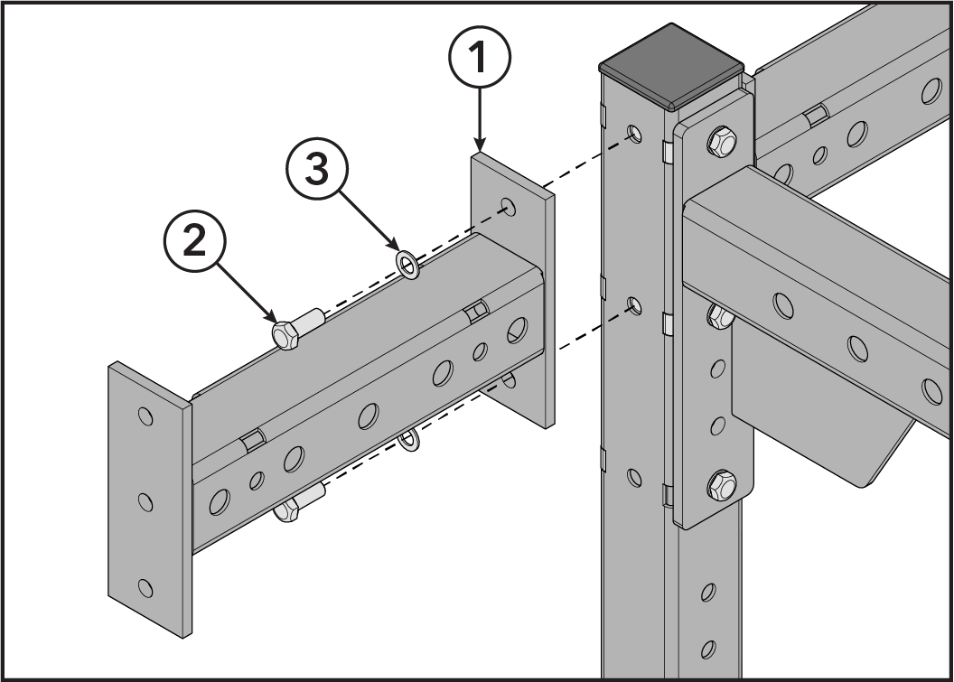
  4. Install bolts, washers, lock nut, and rectangle tubing nut securing stability foot to training upright using two 3/4" wrenches.
    Item Description Qty.
    1 Stability Foot 1
    2 Bolt, 1/2"-13 x 1.25" 1
    3 Bolt, 1/2" x 5 1/2" 1
    4 Lock Washer, 1/2" 3
    5 Lock Nut, 1/2" 1
    6 Rectangle Tubing Nut, 7GA, 3" 1

    Hand tighten hardware.

    Note: Stability feet are designed to lift the training uprights slightly off the floor. This is done to ensure solid contact to the floor at the furthest outside points.
  5. Repeat Steps 1-4 to assemble the opposite uprights and crossmembers.
  6. Stand assembled components upright.
  7. Note: OPTIONAL
    Install bolts, washers, and rectangle tubing nuts securing spider gusset crossmember to bottom of storage uprights using a 3/4" wrench.
    Item Description Qty.
    1 Spider Gusset Crossmember 1
    2 Bolt, 1/2"-13 x 1.25" 4
    3 Lock Washer, 1/2" 4
    4 Rectangle Tubing Nut, 11GA, 3" 6

    Hand tighten hardware.

  8. Install bolts, washers, and rectangle tubing nuts securing rear crossmember to top of storage uprights using a 3/4" wrench.
    Item Description Qty.
    1 Rear Crossmember 1
    2 Bolt, 1/2"-13 x 1.25" 6
    3 Lock Washer, 1/2" 6
    4 Rectangle Tubing Nut, 11GA, 3" 7

    Hand tighten hardware.

  9. Install bolts, washers, and rectangle tubing nuts securing front crossmember to training uprights using a 3/4" wrench.
    Note: 3-Handle Bar front crossmember shown for example.
    Item Description Qty.
    1 Front Crossmember 1
    2 Bolt, 1/2"-13 x 1.25" 6
    3 Lock Washer, 1/2" 6
    4 Rectangle Tubing Nut, 11GA, 3" 2
    5 Rectangle Tubing Nut, 7GA, 3" 3
    6 Rectangle Tubing Nut, 7GA, 4" 4

    Hand tighten hardware.

    Note: Front crossmembers install with different hardware on 9 ft. uprights than on 8 ft. uprights. Below shows how to install to 9 ft. uprights.
    Item Description Qty.
    1 Front Crossmember 1
    2 Bolt, 1/2"-13 x 1.25" 4
    3 Lock Washer, 1/2" 4
    4 Rectangle Tubing Nut, 7GA, 3" 4
    5 Rectangle Tubing Nut, 7GA, 4" 5

    Hand tighten hardware.

2.5.2: Install Extra Hardware

  1. Fill empty slots at top of right training upright with hardware.
    Item Description Qty.
    1 Bolt, 1/2"-13 x 1.25" 3
    2 Lock Washer, 1/2" 3
    3 Rectangle Tubing Nut, 7GA, 3" 3
    4 Rectangle Tubing Nut, 7GA, 4" 1

    Hand tighten hardware.

  2. Fill empty slots at top of left training upright with hardware.
    Item Description Qty.
    1 Bolt, 1/2"-13 x 1.25" 3
    2 Lock Washer, 1/2" 3

    Hand tighten hardware.

  3. Fill empty slots at top of storage uprights with hardware.
    Item Description Qty.
    1 Bolt, 1/2"-13 x 1.25" 12
    2 Lock Washer, 1/2" 12
    3 Rectangle Tubing Nut, 11GA, 3" 6

    Hand tighten hardware.

  4. Fill empty slots at bottom of storage uprights with hardware.
    Item Description Qty.
    1 Bolt, 1/2"-13 x 1.25" 12
    2 Lock Washer, 1/2" 12
    3 Rectangle Tubing Nut, 11GA, 3" 10

    Hand tighten hardware.

2.5.3: Install Anvil Plates

  1. Install Hammer Badge to anvil plates.
    Note: Hammer Badges are only installed on non-custom anvil plates.
    Item Description Qty.
    1 Anvil Plate 2
    2 Hammer Badge 2
  2. Install bolts, washers, and rectangle tubing nuts securing right anvil plate to 8 ft. training upright and upper side crossmember using a 3/4" wrench.
    Item Description Qty.
    1 Right Anvil Plate 1
    2 Bolt, 1/2"-13 x 1.25" 4
    3 Lock Washer, 1/2" 4
    4 Rectangle Tubing Nut, 11GA, 3" 1

    Hand tighten hardware.

  3. Install bolts, washers, and rectangle tubing nuts securing left anvil plate to 8 ft. training upright and upper side crossmember using a 3/4" wrench.
    Item Description Qty.
    1 Left Anvil Plate 1
    2 Bolt, 1/2"-13 x 1.25" 4
    3 Lock Washer, 1/2" 4
    4 Rectangle Tubing Nut, 11GA, 3" 1
    5 Rectangle Tubing Nut, 7GA, 4" 3

    Hand tighten hardware.

  4. Note: The following steps shows how to install anvil plates to 9 ft. training uprights.
    Install bolts, washers, spacer, lock nut, and rectangle tubing nuts securing right anvil plate to 9 ft. training upright and upper side crossmember using a 3/4" wrench.
    Item Description Qty.
    1 Right Anvil Plate 1
    2 Bolt, 1/2" x 4" 1
    3 Bolt, 1/2"-13 x 1.25" 3
    4 Lock Washer, 1/2" 4
    5 Spacer 1
    6 Lock Nut, 1/2" Thin 1
    7 Rectangle Tubing Nut, 7GA, 4" 2

    Hand tighten hardware.

  5. Install bolts, washers, spacers, lock nut, and rectangle tubing nuts securing left anvil plate to 9 ft. training upright and upper side crossmember using a 3/4" wrench.
    Item Description Qty.
    1 Right Anvil Plate 1
    2 Bolt, 1/2" x 4" 1
    3 Bolt, 1/2"-13 x 1.25" 3
    4 Lock Washer, 1/2" 4
    5 Spacer 1
    6 Lock Nut, 1/2" Thin 1
    7 Rectangle Tubing Nut, 7GA, 4" 3

    Hand tighten hardware.

2.5.4: Tighten Hardware

Tighten all loose hardware to 45-50 ft-lb (61-67.8 Nm) in the following order:
  1. Lower stability feet bolts to training uprights.
  2. Upper stability feet bolts to training uprights.
  3. Lower side crossmembers to training and storage uprights.
  4. Optional: Spider gusset crossmember to storage uprights.
  5. Upper rear crossmember to storage uprights.
  6. Upper side crossmembers to training and storage uprights.
  7. Front crossmember to training uprights.
  8. Anvil plates to training uprights.
  9. Extra hardware.

2.6: Component List

Item Description Qty.
1 Training Upright

96" (244 cm) or 108" (274 cm)

2
2 Storage Upright

96" (244 cm) or 108" (274 cm)

2
3 Storage Depth

15" (38 cm), 21" (53 cm) or 34.5" (88 cm)

4
4 Optional: Stability Feet 2
5

Optional: Spider Gusset Crossmember

1
Front Crossmembers
6 3-Handle Bar 1
7 Straight Bar
8 Rotating Chin
9 3x3
10 3x3 with Arc Bar
11 3x3 with Ball Grips
12 3x3 with Neutral Grips
Rear Crossmembers
13 Super Duty with Hammer Strength Sign 1
14 Super Duty with Custom Sign
Bar Catches and Supports
15 HR Bar Catch 1
16 4x3 Bar Support 1
Weight Horns
17 7" Weight Horn Varies
18 11" Weight Horn
19 Bull Horn

2.7: Power Rack (ELT-PR)

Note: If using HR Bar Catches on the outside of training uprights, rack is required to be bolted to floor unless it has stability feet.

2.8: Assembly Procedure

Three or more people will be required for this procedure.

Tip: Read and understand all instructions thoroughly before assembling this unit. Check all items carefully. If there is damage, see the Customer Service section of this manual for proper procedure to return, replace, or reorder parts.

2.8.1: Assemble Training Uprights and Crossmembers

  1. Lay components out on the ground.
    • The Hammer Strength HS cut-out on the training uprights face out when the rack is assembled.
    • Review the Label Locations topic to make sure that the serial number and warning labels etc. are in the appropriate location for each upright when assembling.
  2. Install bolts, washers, and rectangle tubing nuts securing upper PR crossmember to tops of training uprights using a 3/4" wrench.
    Important: Upper PR crossmembers only have holes in the sides.
    Item Description Qty.
    1 Upper PR Crossmember 1
    2 Bolt, 1/2"-13 x 1.25" 4
    3 Lock Washer, 1/2" 4
    4 Rectangle Tubing Nut, 7GA, 3" 4
    5 Rectangle Tubing Nut, 7GA, 4" 4

    Hand tighten hardware.

  3. Install bolts, backing washers, washers, lock nut, and rectangle tubing nuts securing lower PR crossmember to bottoms of training uprights using a 3/4" wrench.
    Important: Lower PR crossmembers have holes in all four sides.
    Item Description Qty.
    1 Lower PR Crossmember 1
    2 Bolt, 1/2"-13 x 1.25" 3
    3 Bolt, 1/2" x 5 1/2" 1
    4 Backing Washer 2
    5 Lock Washer, 1/2" 3
    6 Lock Nut, 1/2" 1
    7 Rectangle Tubing Nut, 7GA, 3" 3

    Hand tighten hardware.

  4. Note: OPTIONAL
    Install bolts, washers, lock nut, and rectangle tubing nuts securing stability foot to training upright using two 3/4" wrenches.
    Item Description Qty.
    1 Stability Foot 1
    2 Bolt, 1/2"-13 x 1.25" 2
    3 Bolt, 1/2" x 5 1/2" 1
    4 Lock Washer, 1/2" 4
    5 Lock Nut, 1/2" 1
    6 Rectangle Tubing Nut, 7GA, 3" 2

    Hand tighten hardware.

    Note: Stability feet are designed to lift the training uprights slightly off the floor. This is done to ensure solid contact to the floor at the furthest outside points.
  5. Repeat Steps 1-4 to assemble the opposite uprights and crossmembers.
  6. Stand assembled components upright.
  7. Install bolts, washers, and rectangle tubing nuts securing 3x3 crossmember to rear training uprights using a 3/4" wrench.
    Item Description Qty.
    1 3x3 Crossmember 1
    2 Bolt, 1/2"-13 x 1.25" 6
    3 Lock Washer, 1/2" 6
    4 Rectangle Tubing Nut, 11GA, 3" 2
    5 Rectangle Tubing Nut, 7GA, 3" 3
    6 Rectangle Tubing Nut, 7GA, 4" 4

    Hand tighten hardware.

  8. Install bolts, washers, and rectangle tubing nuts securing front crossmember to front training uprights using a 3/4" wrench.
    Note: 3-Handle Bar front crossmember shown for example.
    Item Description Qty.
    1 Front Crossmember 1
    2 Bolt, 1/2"-13 x 1.25" 6
    3 Lock Washer, 1/2" 6
    4 Rectangle Tubing Nut, 11GA, 3" 2
    5 Rectangle Tubing Nut, 7GA, 3" 3
    6 Rectangle Tubing Nut, 7GA, 4" 4

    Hand tighten hardware.

2.8.2: Install Extra Hardware

  1. Fill empty slots at top of front right training upright with hardware.
    Item Description Qty.
    1 Bolt, 1/2"-13 x 1.25" 3
    2 Lock Washer, 1/2" 3
    3 Rectangle Tubing Nut, 7GA, 3" 3

    Hand tighten hardware.

  2. Fill empty slots at top of front left training upright with hardware.
    Item Description Qty.
    1 Bolt, 1/2"-13 x 1.25" 3
    2 Lock Washer, 1/2" 3

    Hand tighten hardware.

2.8.3: Install Anvil Plates

  1. Install Hammer Badge to anvil plates.
    Note: Hammer Badges are only installed on non-custom anvil plates.
    Item Description Qty.
    1 Anvil Plate 2
    2 Hammer Badge 2
  2. Install bolts, washers, and rectangle tubing nuts securing right anvil plate to front right training upright and upper PR crossmember using a 3/4" wrench.
    Item Description Qty.
    1 Right Anvil Plate 1
    2 Bolt, 1/2"-13 x 1.25" 4
    3 Lock Washer, 1/2" 4
    4 Rectangle Tubing Nut, 11GA, 3" 1
    5 Rectangle Tubing Nut, 7GA, 4" 1

    Hand tighten hardware.

  3. Install bolts, washers, and rectangle tubing nuts securing left anvil plate to front left training upright and upper PR crossmember using a 3/4" wrench.
    Item Description Qty.
    1 Left Anvil Plate 1
    2 Bolt, 1/2"-13 x 1.25" 4
    3 Lock Washer, 1/2" 4
    4 Rectangle Tubing Nut, 11GA, 3" 1
    5 Rectangle Tubing Nut, 7GA, 4" 3

    Hand tighten hardware.

  4. Install bolts, washers, and rectangle tubing nuts securing right anvil plate to rear left training upright and upper PR crossmember using a 3/4" wrench.
    Item Description Qty.
    1 Right Anvil Plate 1
    2 Bolt, 1/2"-13 x 1.25" 4
    3 Lock Washer, 1/2" 4
    4 Rectangle Tubing Nut, 11GA, 3" 1
    5 Rectangle Tubing Nut, 7GA, 3" 2
    6 Rectangle Tubing Nut, 7GA, 4" 1

    Hand tighten hardware.

  5. Install bolts, washers, and rectangle tubing nuts securing left anvil plate to rear right training upright and upper PR crossmember using a 3/4" wrench.
    Item Description Qty.
    1 Left Anvil Plate 1
    2 Bolt, 1/2"-13 x 1.25" 4
    3 Lock Washer, 1/2" 4
    4 Rectangle Tubing Nut, 11GA, 3" 1
    5 Rectangle Tubing Nut, 7GA, 4" 3

    Hand tighten hardware.

2.8.4: Assemble Storage Uprights

  1. Lay storage components out on the ground.
    • The feet on the storage uprights point backward when the rack is assembled.
    • Review the Label Locations topic to make sure that the serial number and warning labels etc. are in the appropriate location for each upright when assembling.
    Note: The feet on the storage uprights point backward when the rack is assembled.
  2. Install bolts, washers, and rectangle tubing nuts securing upper side crossmember to top of storage upright using a 3/4" wrench.
    Important: Upper side crossmembers only have holes in the sides.
    Item Description Qty.
    1 Upper Side Crossmember 1
    2 Bolt, 1/2"-13 x 1.25" 2
    3 Lock Washer, 1/2" 2
    4 Rectangle Tubing Nut, 11GA, 3" 4

    Hand tighten hardware.

  3. Install bolts, washers, and rectangle tubing nuts securing lower side crossmember to bottom of storage upright using a 3/4" wrench.
    Important: Lower side crossmembers have holes in all four sides.
    Item Description Qty.
    1 Lower Side Crossmember 1
    2 Bolt, 1/2"-13 x 1.25" 2
    3 Lock Washer, 1/2" 2
    4 Rectangle Tubing Nut, 11GA, 3" 2

    Hand tighten hardware.

  4. Stand assembled components upright and align with training uprights.
  5. Install bolts, washers, lock nut, and rectangle tubing nut securing lower side crossmember to bottom of rear training upright using two 3/4" wrenches.
    Item Description Qty.
    1 Lower Side Crossmember 1
    2 Bolt, 1/2"-13 x 1.25" 1
    3 Bolt, 1/2" x 5 1/2" 1
    4 Lock Washer, 1/2" 3
    5 Lock Nut, 1/2" 1
    6 Rectangle Tubing Nut, 7GA, 3" 1

    Hand tighten hardware.

  6. Install bolts and washers securing upper side crossmember to top of rear training upright using a 3/4" wrench.
    Item Description Qty.
    1 Upper Side Crossmember 1
    2 Bolt, 1/2"-13 x 1.25" 2
    3 Lock Washer, 1/2" 2

    Hand tighten hardware.

  7. Note: OPTIONAL
    Install bolts, washers, and rectangle tubing nuts securing spider gusset crossmember to storage uprights using a 3/4" wrench.
    Item Description Qty.
    1 Spider Gusset Crossmember 1
    2 Bolt, 1/2"-13 x 1.25" 4
    3 Lock Washer, 1/2" 4
    4 Rectangle Tubing Nut, 11GA, 3" 6

    Hand tighten hardware.

  8. Install bolts, washers, and rectangle tubing nuts securing rear crossmember to storage uprights using a 3/4" wrench.
    Item Description Qty.
    1 Rear Crossmember 1
    2 Bolt, 1/2"-13 x 1.25" 6
    3 Lock Washer, 1/2" 6
    4 Rectangle Tubing Nut, 11GA, 3" 7

    Hand tighten hardware.

2.8.5: Install Extra Hardware

  1. Fill empty slots at top of storage uprights with hardware.
    Item Description Qty.
    1 Bolt, 1/2"-13 x 1.25" 12
    2 Lock Washer, 1/2" 12
    3 Rectangle Tubing Nut, 11GA, 3" 6

    Hand tighten hardware.

  2. Fill empty slots at bottom of storage uprights with hardware.
    Item Description Qty.
    1 Bolt, 1/2"-13 x 1.25" 12
    2 Lock Washer, 1/2" 12
    3 Rectangle Tubing Nut, 11GA, 3" 10

    Hand tighten hardware.

2.8.6: Tighten Hardware

Tighten all loose hardware to 45-50 ft-lb (61-67.8 Nm) in the following order:
  1. Optional: Lower stability feet bolts to training uprights.
  2. Optional: Upper stability feet bolts to training uprights.
  3. Lower side crossmembers to training and storage uprights.
    Note: Bolts with backing washers should be tightened to 20-25 ft-lb (27-34 Nm)
  4. Optional: Spider gusset crossmember to storage uprights.
  5. Upper rear crossmember to storage uprights.
  6. Upper side crossmembers to training and storage uprights.
  7. Front crossmember to training uprights.
  8. Anvil plates to training uprights.
  9. Extra hardware.

2.9: Component List

Item Description Qty.
1 Training Upright

96" (244 cm) or 108" (274 cm)

4
2 Storage Upright

96" (244 cm) or 108" (274 cm)

2
3 Training Depth

34.5" (88 cm) or 42" (107 cm)

4
4 Storage Depth

15" (38 cm), 21" (53 cm) or 34.5" (88 cm)

4
5 Optional: Stability Feet 2
6 Optional: Spider Gusset Crossmember 1
Front Crossmembers
7 3-Handle Bar 1
8 Straight Bar
9 Rotating Chin
10 3x3
11 3x3 with Arc Bar
12 3x3 with Ball Grips
13 3x3 with Neutral Grips
Rear Crossmembers
14 Super Duty with Hammer Strength Sign 1
15 Super Duty with Custom Sign
Bar Catches
16 HR Bar Catch 2
17 PR Bar Catch 2
18 PR Flexible Bar Catch 2
Bar Supports
19 4x3 Bar Support 4
Weight Horns
20 7" Weight Horn Varies
21 11" Weight Horn
22 Bull Horn

2.10: Combo Rack (ELT-HHCR, ELT-PHCR, ELT-PPCR)

Half / Half Combo Rack (ELT-HHCR)
Note: Half / Half Combo Rack required to be bolted to floor unless ordered with Stability Feet option.
Power / Half Combo Rack (ELT-PHCR)
Note: Power / Half Combo Rack required to be bolted to floor unless ordered with Stability Feet option.
Power / Power Combo Rack (ELT-PPCR)
Note: Power / Power Combo Rack is not required to be bolted to floor.

2.11: Assembly Procedure

Four or more people will be required for this procedure.

Tip: Read and understand all instructions thoroughly before assembling this unit. Check all items carefully. If there is damage, see the Customer Service section of this manual for proper procedure to return, replace, or reorder parts.
Note: The Half / Half Combo Rack is shown for example. Other Combo Racks can be assembled using the same procedure.

2.11.1: Assemble First Half Rack

2.11.1.1: Assemble Uprights and Crossmembers

  1. Lay components out on the ground.
    • The Hammer Strength HS cut-out on the training uprights face out when the rack is assembled.
    • Review the Label Locations topic to make sure that the serial number and warning labels etc. are in the appropriate location for each upright when assembling.
    Item Description Qty.
    1 Storage Upright 1
    2 Training Upright 1
  2. Install bolts, washers, and rectangle tubing nuts securing upper side crossmember to tops of training upright and storage upright using a 3/4" wrench.
    Important: Upper side crossmembers only have holes in the sides and Hammer Lock slots on top.
    Item Description Qty.
    1 Upper Side Crossmember 1
    2 Bolt, 1/2"-13 x 1.25" 4
    3 Lock Washer, 1/2" 4
    4 Rectangle Tubing Nut, 11GA, 3" 4
    5 Rectangle Tubing Nut, 7GA, 3" 2
    6 Rectangle Tubing Nut, 7GA, 4" 2

    Hand tighten hardware.

    Note: Removing end caps at tops of storage and training uprights will help give access to Hammer Locks inside tube. Use a screwdriver to push end caps out from upright tube. Press end caps back into upright tube after bolts are installed.
  3. Install bolts, washers, and rectangle tubing nuts securing lower side crossmember to bottoms of training upright and storage upright using a 3/4" wrench.
    Important: Lower side crossmembers have holes in all four sides.
    Item Description Qty.
    1 Lower Side Crossmember 1
    2 Bolt, 1/2"-13 x 1.25" 3
    3 Lock Washer, 1/2" 3
    4 Rectangle Tubing Nut, 11GA, 3" 2
    5 Rectangle Tubing Nut, 7GA, 3" 1

    Hand tighten hardware.

  4. Install bolts, washers, lock nut, and rectangle tubing nut securing stability foot to training upright using two 3/4" wrenches.
    Item Description Qty.
    1 Stability Foot 1
    2 Bolt, 1/2"-13 x 1.25" 1
    3 Bolt, 1/2" x 5 1/2" 1
    4 Lock Washer, 1/2" 3
    5 Lock Nut, 1/2" 1
    6 Rectangle Tubing Nut, 7GA, 3" 1

    Hand tighten hardware.

    Note: Stability feet are designed to lift the training uprights slightly off the floor. This is done to ensure solid contact to the floor at the furthest outside points.
  5. Repeat Steps 1-4 to assemble the opposite uprights and crossmembers.
  6. Stand assembled components upright.
  7. Install bolts, washers, and rectangle tubing nuts securing rear crossmember to top of storage uprights using a 3/4" wrench.
    Item Description Qty.
    1 Rear Crossmember 1
    2 Bolt, 1/2"-13 x 1.25" 6
    3 Lock Washer, 1/2" 6
    4 Rectangle Tubing Nut, 11GA, 3" 7

    Hand tighten hardware.

  8. Install bolts, washers, and rectangle tubing nuts securing front crossmember to training uprights using a 3/4" wrench.
    Note: 3-Handle Bar front crossmember shown for example.
    Item Description Qty.
    1 Front Crossmember 1
    2 Bolt, 1/2"-13 x 1.25" 6
    3 Lock Washer, 1/2" 6
    4 Rectangle Tubing Nut, 11GA, 3" 2
    5 Rectangle Tubing Nut, 7GA, 3" 3
    6 Rectangle Tubing Nut, 7GA, 4" 4

    Hand tighten hardware.

    Note: Front crossmembers install with different hardware on 9 ft. uprights than on 8 ft. uprights. Below shows how to install to 9 ft. uprights.
    Item Description Qty.
    1 Front Crossmember 1
    2 Bolt, 1/2"-13 x 1.25" 4
    3 Lock Washer, 1/2" 4
    4 Rectangle Tubing Nut, 7GA, 3" 4
    5 Rectangle Tubing Nut, 7GA, 4" 5

    Hand tighten hardware.

2.11.1.2: Install Extra Hardware

  1. Fill empty slots at top of right training upright with hardware.
    Item Description Qty.
    1 Bolt, 1/2"-13 x 1.25" 3
    2 Lock Washer, 1/2" 3
    3 Rectangle Tubing Nut, 7GA, 3" 3
    4 Rectangle Tubing Nut, 7GA, 4" 1

    Hand tighten hardware.

  2. Fill empty slots at top of left training upright with hardware.
    Item Description Qty.
    1 Bolt, 1/2"-13 x 1.25" 3
    2 Lock Washer, 1/2" 3

    Hand tighten hardware.

  3. Fill empty slots at top of storage uprights with hardware.
    Item Description Qty.
    1 Bolt, 1/2"-13 x 1.25" 6
    2 Lock Washer, 1/2" 6
    3 Rectangle Tubing Nut, 11GA, 3" 3

    Hand tighten hardware.

  4. Fill empty slots at bottom of storage uprights with hardware.
    Item Description Qty.
    1 Bolt, 1/2"-13 x 1.25" 8
    2 Lock Washer, 1/2" 8
    3 Rectangle Tubing Nut, 11GA, 3" 8

    Hand tighten hardware.

2.11.1.3: Install Anvil Plates

  1. Install Hammer Badge to anvil plates.
    Note: Hammer Badges are only installed on non-custom anvil plates.
    Item Description Qty.
    1 Anvil Plate 2
    2 Hammer Badge 2
  2. Install bolts, washers, and rectangle tubing nuts securing right anvil plate to 8 ft. training upright and upper side crossmember using a 3/4" wrench.
    Item Description Qty.
    1 Right Anvil Plate 1
    2 Bolt, 1/2"-13 x 1.25" 4
    3 Lock Washer, 1/2" 4
    4 Rectangle Tubing Nut, 11GA, 3" 1

    Hand tighten hardware.

  3. Install bolts, washers, and rectangle tubing nuts securing left anvil plate to 8 ft. training upright and upper side crossmember using a 3/4" wrench.
    Item Description Qty.
    1 Left Anvil Plate 1
    2 Bolt, 1/2"-13 x 1.25" 4
    3 Lock Washer, 1/2" 4
    4 Rectangle Tubing Nut, 11GA, 3" 1
    5 Rectangle Tubing Nut, 7GA, 4" 3

    Hand tighten hardware.

  4. Note: The following steps shows how to install anvil plates to 9 ft. training uprights.
    Install bolts, washers, spacer, lock nut, and rectangle tubing nuts securing right anvil plate to 9 ft. training upright and upper side crossmember using a 3/4" wrench.
    Item Description Qty.
    1 Right Anvil Plate 1
    2 Bolt, 1/2" x 4" 1
    3 Bolt, 1/2"-13 x 1.25" 3
    4 Lock Washer, 1/2" 4
    5 Spacer 1
    6 Lock Nut, 1/2" Thin 1
    7 Rectangle Tubing Nut, 7GA, 4" 2

    Hand tighten hardware.

  5. Install bolts, washers, spacers, lock nut, and rectangle tubing nuts securing left anvil plate to 9 ft. training upright and upper side crossmember using a 3/4" wrench.
    Item Description Qty.
    1 Right Anvil Plate 1
    2 Bolt, 1/2" x 4" 1
    3 Bolt, 1/2"-13 x 1.25" 3
    4 Lock Washer, 1/2" 4
    5 Spacer 1
    6 Lock Nut, 1/2" Thin 1
    7 Rectangle Tubing Nut, 7GA, 4" 3

    Hand tighten hardware.

2.11.2: Assemble Second Half Rack

2.11.2.1: Half / Half Combo Rack with Double Storage

If assembling a Half / Half Combo Rack with Double Storage, repeat previous steps to assemble second Half Rack.

2.11.2.2: Half / Half Combo Rack with Single Storage

  1. Install bolts, washers, and rectangle tubing nuts securing upper side crossmember to top of training upright using a 3/4" wrench.
    Item Description Qty.
    1 Upper Side Crossmember 1
    2 Bolt, 1/2"-13 x 1.25" 2
    3 Lock Washer, 1/2" 2
    4 Rectangle Tubing Nut, 7GA, 3" 2
    5 Rectangle Tubing Nut, 7GA, 4" 2

    Hand tighten hardware.

  2. Install bolts, washers, lock nut, and rectangle tubing nuts securing lower side crossmember and stability foot to bottom of training upright using a 3/4" wrench.
    Item Description Qty.
    1 Lower Side Crossmember 1
    2 Stability Foot 1
    3 Bolt, 1/2"-13 x 1.25" 2
    4 Bolt, 1/2" x 5 1/2" 1
    5 Lock Washer, 1/2" 4
    6 Lock Nut, 1/2" 1
    7 Rectangle Tubing Nut, 7GA, 3" 2

    Hand tighten hardware.

  3. Repeat Steps 1 and 2 to assemble the opposite upright, crossmembers, and stability foot.
  4. Stand assembled components upright.

2.11.3: Install Half Rack to Half Rack

The followings steps show how to install the first Half Rack to second Half Rack with Double Storage.
  1. Install bolts and washers securing lower side crossmember to bottom of storage upright using a 3/4" wrench.
    Item Description Qty.
    1 Lower Side Crossmember 1
    2 Bolt, 1/2"-13 x 1.25" 2
    3 Lock Washer, 1/2" 2

    Hand tighten hardware.

  2. Install bolts and washers securing upper side crossmember to top of storage upright using a 3/4" wrench.
    Item Description Qty.
    1 Upper Side Crossmember 1
    2 Bolt, 1/2"-13 x 1.25" 2
    3 Lock Washer, 1/2" 2

    Hand tighten hardware.

  3. Repeat Steps 1 & 2 to install side crossmembers to opposite storage upright.
  4. Align two assembled Half Racks.
    Half Rack / Half Rack with Double Storage
    Note: On units with Double Storage options, the feet on the storage uprights face each other when assembled.
  5. Install bolts and washers securing lower side crossmember to bottom of storage upright using a 3/4" wrench.
    Item Description Qty.
    1 Bolt, 1/2"-13 x 1.25" 2
    2 Lock Washer, 1/2" 2

    Hand tighten hardware.

  6. Install bolts and washers securing upper side crossmember to top of storage upright using a 3/4" wrench.
    Item Description Qty.
    1 Bolt, 1/2"-13 x 1.25" 2
    2 Lock Washer, 1/2" 2

    Hand tighten hardware.

  7. Repeat Steps 5 & 6 to install side crossmembers to opposite storage upright.

The following steps show how to install the Half Rack to Half Rack with Single Storage.
  1. Align single storage assemblies with assembled Half Rack.
    Half Rack / Half Rack with Single Storage
  2. Install bolts and washers securing lower side crossmember to bottom of storage upright using a 3/4" wrench.
    Item Description Qty.
    1 Lower Side Crossmember 1
    2 Bolt, 1/2"-13 x 1.25" 2
    3 Lock Washer, 1/2" 2

    Hand tighten hardware.

  3. Install bolts and washers securing upper side crossmember to top of storage upright using a 3/4" wrench.
    Item Description Qty.
    1 Upper Side Crossmember 1
    2 Bolt, 1/2"-13 x 1.25" 2
    3 Lock Washer, 1/2" 2

    Hand tighten hardware.

  4. Repeat Steps 2 & 3 to install side crossmembers to opposite storage upright.
  5. Install bolts, washers, and rectangle tubing nuts securing front crossmember to training uprights using a 3/4" wrench.
    Note: 3-Handle Bar front crossmember shown for example.
    Item Description Qty.
    1 Front Crossmember 1
    2 Bolt, 1/2"-13 x 1.25" 6
    3 Lock Washer, 1/2" 6
    4 Rectangle Tubing Nut, 11GA, 3" 2
    5 Rectangle Tubing Nut, 7GA, 3" 3
    6 Rectangle Tubing Nut, 7GA, 4" 4

    Hand tighten hardware.

  6. Repeat steps from Install Anvil Plates to install anvil plates to second Half Rack.

2.11.4: Tighten Hardware

Tighten all loose hardware to 45-50 ft-lb (61-67.8 Nm) in the following order:
  1. Lower stability feet bolts to training uprights.
  2. Upper stability feet bolts to training uprights.
  3. Lower side crossmembers to training and storage uprights.
  4. Upper rear crossmember to storage uprights.
  5. Upper side crossmembers to training and storage uprights.
  6. Front crossmember to training uprights.
  7. Anvil plates to training uprights.
  8. Extra hardware.

2.12: Component List

Item Description Qty.
Combo Racks consist of components from the Half Rack or Power Rack .

2.13: Optional Components

2.13.1: Install Custom Sign

The super duty crossmember is required to install the custom sign.
  1. Install screws, washers, spacers, and lock nuts securing optional custom sign and backer plate to super duty crossmember using a 7mm Allen wrench and 17mm wrench.
    Note: Single custom sign can be installed on the front or rear of super duty crossmember.
    Single Custom Sign
    Double Custom Sign
    Item Description Qty.
    1 Super Duty Crossmember 1
    2 Custom Sign 1 or 2
    3 Backer Plate 1 or 2
    4 Screw, M10 x 1.5, 25mm 2
    5 Screw, M10 x 1.5, 30mm 2
    6 Screw, M10 x 1.5, 35mm 4
    7 Flat Washer, 3/8" 8
    8 Lock Nut, M10 4
    9 Spacer 2

    Tighten hardware to 40-50 in-lb (4.5-5.6 Nm).

2.13.2: Install Flexible Bar Catches

Flexible bar catches can be installed to Power Racks, Power / Half Combo Racks, and Power / Power Combo Racks.
  1. Install flexible bar catches to training uprights by lifting the latch and sliding the pivot shaft into training upright hole.
    Item Description Qty.
    1 Latch 4
    2 Pivot Shaft 4
    3 Training Upright 4
    Note: Latches are designed to go over the top of pivot shafts.
    Correct Latch Direction
    Incorrect Latch Direction
    Note: Do NOT offset flexible bar catches more than three hole positions.

2.13.3: Install Weight Horns

Weight Horn Options
Note: Weight horns and bull horns are sold in pairs.
Item Description
1 7" Weight Horn
2 11" Weight Horn
3 Bull Horn
  1. Install bolts, washers, backing washers, lock nuts, and rectangle tubing nuts securing weight horns to storage uprights using two 3/4" wrenches.
    Important: Confirm weight horns are angled upwards when installing.
    Note: The bottom two weight horns are installed using rectangle tubing nuts.
    Item Description Qty.
    1 Weight Horn 10
    2 Storage Upright 2
    3 Bolt, 1/2"-13 x 1.25" 8
    4 Bolt, 1/2" x 4 1/2" 12
    5 Lock Washer, 1/2" 20
    6 Backing Washer 12
    7 Lock Nut, 1/2" 12
    8 Rectangle Tubing Nut, 11GA, 3" 8
  2. Tighten Bolts, 1/2" x 4 1/2" to 20-25 ft-lb (27-34 Nm).
  3. Tighten Bolts, 1/2"-13 x 1.25" to 45-50 ft-lb (61-67.8 Nm).

5 Weight Horn

Olympic Plate Configuration

5 Bull Horn

Olympic Plate Configuration

Note: 5 bull horn configuration can only be installed to Combo Racks with Single Storage.

2.13.4: Weight Plate Storage

When adding and removing weight plates from weight horns, always evenly load and unload (left/right side) weight plates to avoid tipping.

Below is the recommended bumper plate storage configuration:

(2) 10 lb plates

(2) 25 lb plates

(2) 45 lb plates

(4) 45 lb plates

Below is the recommended Olympic plate storage configuration:

(2) 2.5 lb or 5 lb plates

(2) 10 lb plates

(2) 25 lb plates

(2) 45 lb plates

(4) 45 lb plates

2.13.5: Install Modular Storage

Tray Options
Item Description
1 Powerblock Tray (top position only)
2 Bumper Tray (recommended top or bottom position)
3 Accessory Tray (recommended top or bottom position)
  1. Install bolts, washers, and lock nuts securing crossmember to side frames using two 3/4" wrenches.
    Item Description Qty.
    1 Side Frame 2
    2 Crossmember 1
    3 Bolt, 1/2" x 4" 4
    4 Lock Washer, 1/2" 8
    5 Lock Nut, 1/2" Thin 4

    Hand tighten hardware.

  2. Install bolts, washers, and lock nuts securing bottom tray to side frames using two 3/4" wrenches.
    Item Description Qty.
    1 Bottom Tray 1
    2 Bolt, 1/2" x 4" 4
    3 Lock Washer, 1/2" 8
    4 Lock Nut, 1/2" Thin 4

    Hand tighten hardware.

  3. Install bolts, washers, and lock nuts securing top tray to side frames using two 3/4" wrenches.
    Item Description Qty.
    1 Top Tray 1
    2 Bolt, 1/2" x 4" 4
    3 Lock Washer, 1/2" 8
    4 Lock Nut, 1/2" Thin 4

    Hand tighten hardware.

    Note: Bumper and accessory trays should rest flat when installed on side frames. If tray is inclined, it was installed backwards.
    Correct Tray Orientation
    Incorrect Tray Orientation
  4. Tighten all loose hardware to 20-25 ft-lb (27-34 Nm).
  5. Install bolts, washers, backing washers, and lock nuts securing modular storage assembly to storage upright using two 3/4" wrenches.
    WITH Spider Gusset Crossmember
    WITHOUT Spider Gusset Crossmember
    Item Description Qty.
    1 Modular Storage Assembly 1
    2 Storage Upright 1
    3 Bolt, 1/2" x 5 1/2" 1
    4 Backing Washer 1 or 2
    5 Lock Washer, 1/2" 0 or 1
    6 Lock Nut, 1/2" Thin 1

    Tighten hardware to 10-15 ft-lb (13-20 Nm).

Note: Weight horns and bull horns should be configured in the following hole locations to allow space for modular storage trays.
Weight Horn Configuration
Bull Horn and Weight Horn Configuration

2.13.6: Install Wing

  1. Insert the 11-gauge 3-inch rectangular tubing nuts into the 3-handle bar.
    Item Description Qty.
    1 3-Handle Bar 1
    2 Rectangle Tubing Nut, 11GA, 3" 4
  2. Carefully place the ballistic wing on top of the 3-handle bar, then fasten with the connecting hardware and tighten to 45-50 ft-lb (61-67.8 Nm).
    Item Description Qty.
    1 Ballistic Wing 1
    2 Bolt, 1/2"-13 x 1.25" 4
    3 Lock Washer, 1/2" 8
    4 Lock Nut, 1/2" Thin 4
    5 Bolt, 1/2" x 4" 4
    6 Washer: Step, 1/2 In, 0.20 4
    7 3-Handle Bar 1

Chapter 3: Product Information

3.1: Half Rack (ELT-HR)

Product Specs
*Size (L x W x H): in = 56 x 73 x 96 cm =142 x 185 x 244
Live Area (L x W): in = 84 x 120 cm = 213 x 305
Rack Weight: 475 lbs 215 kg
Max User Weight: 400 lbs 181 kg
Max Training Weight: 855 lbs 380 kg
Training Upright Heights: in = 96 or 108 cm = 244 or 274
Storage Upright Height: in = 96 cm = 244
    Note:
  • Length (L) varies depending on Depth Connector size and bolt-to-floor option.
  • Width (W) includes attached weight horns.
  • Height (H) varies depending on Training Upright size.

3.2: Power Rack (ELT-PR)

Product Specs
*Size (L x W x H): in = 64 x 73 x 96 cm =163 x 185 x 244
Live Area (L x W): in = 120 x 120 cm = 305 x 305
Rack Weight: 650 lbs 295 kg
Max User Weight: 400 lbs 181 kg
Max Training Weight: 855 lbs 380 kg
Training Upright Heights: in = 96 or 108 cm = 244 or 274
Storage Upright Height: in = 96 cm = 244
    Note:
  • Length (L) varies depending on Depth Connector size and bolt-to-floor option.
  • Width (W) includes attached weight horns.
  • Height (H) varies depending on Training Upright size.

3.3: Combo Rack (ELT-HHCR, ELT-PHCR, ELT-PPCR)

Half / Half Combo Rack (ELT-HHCR)
  Short Single Storage Long Single Storage Short Double Storage Long Double Storage
Size (L x W): in = 91 x 48

cm = 231 x 122

in = 103 x 48

cm = 262 x 122

in = 109 x 48

cm = 277 x 122

in = 121 x 48

cm = 307 x 122

Live Area (L x W): in = 185 x 120

cm = 470 x 305

in = 197 x 120

cm = 500 x 305

in = 203 x 120

cm = 516 x 305

in = 215 x 120

cm = 546 x 305

Rack Weight: 874 lbs

396 kg

891 lbs

404 kg

1045 lbs

474 kg

1154 lbs

523 kg

Power / Half Combo Rack (ELT-PHCR)
  Short Single Storage Long Single Storage Short Double Storage Long Double Storage
Size (L x W): in = 104.5 x 48

cm = 265 x 122

in = 116.5 x 48

cm = 296 x 122

in = 122.5 x 48

cm = 311 x 122

in = 134.5 x 48

cm = 342 x 122

Live Area (L x W): in = 197.5 x 120

cm = 502 x 305

in = 209.5 x 120

cm = 532 x 305

in = 215.5 x 120

cm = 547 x 305

in = 227.5 x 120

cm = 578 x 305

Rack Weight: 1068 lbs

484 kg

1085 lbs

492 kg

1239 lbs

562 kg

1291 lbs

586 kg

Power / Power Combo Rack (ELT-PPCR)
  Short Single Storage Long Single Storage Short Double Storage Long Double Storage
Size (L x W): in = 118 x 48

cm = 300 x 122

in = 130 x 48

cm = 330 x 122

in = 136 x 48

cm = 345 x 122

in = 148 x 48

cm = 376 x 122

Live Area (L x W): in = 210 x 120

cm = 533 x 305

in = 222 x 120

cm = 564 x 305

in = 228 x 120

cm = 579 x 305

in = 240 x 120

cm = 610 x 305

Rack Weight: 1234 lbs

560 kg

1251 lbs

567 kg

1433 lbs

650 kg

1541 lbs

699 kg

General Product Specs
Max User Weight: 400 lbs 181 kg
Max Training Weight: 855 lbs 380 kg
Training Upright Heights: in = 96 or 108 cm = 244 or 274
Storage Upright Height: in = 96 cm = 244
    Note:
  • All Half / Half Combo Rack depths have 2 pairs of stability feet, increasing the depth by 50" (127 cm).
  • All Power / Half Combo Rack depths have 1 pair of stability feet, increasing the depth by 25" (64 cm).
  • Bolting the Combo Racks to the floor allows all stability feet to be removed.
  • Width and Weight include weight horns.
Half / Half Combo Rack (ELT-HHCR) with Long Double Storage
Power / Half Combo Rack (ELT-PHCR) with Long Double Storage
Power / Power Combo Rack (ELT-PPCR) with Long Double Storage

Chapter 4: Exercise

4.1: General Exercise Information

Intended Use

The intended commercial use of this machine is to aid exercise and improve general physical fitness. Multiple exercises can be performed using this product. It is the responsibility of the owner to ensure exercisers understand general use and only perform recommended exercises that do not compromise the stability of the product or put the user as risk.

Prior to Exercise

Prior to starting a training program, get a complete physical exam to make sure your physician agrees that you are ready. Always warm-up your muscles before a workout. A cardio warm-up followed by stretching is typically recommended.

Start Your Program Conservatively

Choose weights you can easily lift in the first several weeks. Typically, a full range of motion is recommended, but consult a qualified professional if you have questions about whether a full range of motion is appropriate for you due to existing limitations, injury or discomfort. Injuries to health may result from incorrect or excessive training.

A “repetition” (rep) is defined as one complete movement through an exercise, returning to the start position. A “set” is a continuous series of reps, usually between 6-15. During your workout the number of reps you perform in a set depends on your goal. To build muscle and strength, often fewer reps (6 - 8) with heavier weight is recommended in each set. To build endurance, more reps (12-15) with lighter weight is typically recommended.

At the end of your workout, cool down in a similar way to your warm-up.

Chapter 5: Maintenance Procedures

5.1: Maintenance Schedule

ACTION DAILY WEEKLY MONTHLY AS NEEDED
WAX
Frames      
INSPECT
Accessories      
Paint      
Hardware      
Frame      
Clean
  • Frame with a mild soap and water.
Wax
  • Frames with a standard, non-abrasive, wax finish.
Inspect
  • Hardware. Check for loosening. Tighten as required.
  • Frames. Inspect for wear and damage.
  • For paint chips. Fill in immediately with manufacturers touch-up paint.
  • Straps for Power Rack Flexible Bar Catches to be inspected for cuts, frays, or other damage. Any strap showing sign of damage should be replaced immediately.
Once a Week
  • Visually inspect all hardware for loosening, tampering or wear.
  • Inspect all accessories, connecting links, and carabiner clips for wear.
Once a Month
  • Inspect hardware on all machines and tighten any bolts or nuts that may have loosened over the life of the product.
Notes
  • Use polishing compound (such as car wax) and remove shoe scuffs from powder coated surfaces as necessary.
Approved and Compatible Cleaners

Two preferred cleaners have been approved by reliability experts: PureGreen 24 and Gym Wipes. Both cleaners will safely and effectively remove dirt, grime and sweat from equipment. PureGreen 24 and the Antibacterial Force formula of Gym Wipes are both disinfectants that are effective against MRSA and H1N1.

PureGreen 24 is available in a spray which is convenient to use. Apply the spray to a microfiber cloth and wipe down the equipment. Use PureGreen 24 on the equipment for at least 2 minutes for general disinfection purposes and at least 10 minutes for fungus and viral control.

Gym Wipes are large, durable pre-moistened wipes to use on the equipment before and after workouts. Use Gym Wipes on the equipment for at least 2 minutes for general disinfection purposes.

Contact Customer Support Services to order these cleaners (1-800-351-3737 or email: customersupport@lifefitness.com).

Mild soap and water or a mild non-abrasive household cleaner can also be used to clean the display and all exterior surfaces. Use a soft microfiber cloth only. Apply the cleaner to the microfiber cloth before cleaning. DO NOT use ammonia or acid based cleaners. DO NOT use abrasive cleaners. DO NOT use paper towels. DO NOT apply cleaners directly to the equipment surfaces.

Removal of Paint, Marking Pens, or Labels
  • Butyl cellosolve works well for removal of paints, marking pen inks, lipstick, etc.
  • Labels, stickers, etc. may be removed using kerosene. When the solvent will not penetrate sticker material, apply heat (hair dryer) to soften the adhesive and promote removal. GASOLINE SHOULD NOT BE USED.

Chapter 6: Warranty

6.1: What is Covered

This Life Fitness commercial exercise equipment product is warranted to be free of all defects in material and workmanship.

6.2: Who is Covered

The original purchaser or any person receiving the product as a gift from the original purchaser.

6.3: Who Pays Transportation and Insurance For Service

If the Product or any covered part must be returned to a service facility for repairs, We, Life Fitness , will pay all transportation and insurance charges for the first year. You are responsible for transportation and insurance charge after the first year.

6.4: What We Will Do To Correct Covered Defects

We will ship to you any new or rebuilt replacement part or component, or at our option, replace the Product. Such replacement parts are warranted for the remaining portion of the original warranty period.

6.5: What is Not Covered

Any failures or damage caused by unauthorized service, misuse, accident, negligence, improper assembly or installation, debris resulting from any construction activities in the Product’s environment, rust or corrosion as a result of the Product’s location, alterations or modifications without our written authorization, or by failure on your part to use, operate and maintain the Product as set out in your Operation Manual.

All terms of this warranty are void if this product is moved beyond the continental borders of the United States of America (excluding Alaska, Hawaii and Canada) and are then subject to the terms provided by that country’s local authorized Life Fitness representative.

6.6: Owner's Manual

It is VERY IMPORTANT THAT YOU READ THIS MANUAL before operating the Product. Remember to perform the periodic maintenance requirements specified in the Manual to assure proper operation and your continued satisfaction.

6.7: Exclusive Warranty

THIS LIMITED WARRANTY IS IN LIEU OF ALL OTHER WARRANTIES OF ANY KIND EITHER EXPRESSED OR IMPLIED, INCLUDING BUT NOT LIMITED TO THE IMPLIED WARRANTIES OF MERCHANTABILITY AND FITNESS FOR A PARTICULAR PURPOSE, AND ALL OTHER OBLIGATIONS OR LIABILITIES ON OUR PART. We neither assume nor authorize any person to assure for us any other obligation or liability concerning the sale of this Product. Under no circumstances shall we be liable under this warranty, or otherwise, of any damage to any person or property, including any lost profits or lost savings, for any special, indirect, secondary, incidental or consequential damages of any nature arising out of the use of or inability to use this Product. Some states do not allow the exclusion or limitation of implied warranties or of liability for incidental or consequential damages, so the above limitations or exclusions may not apply to you. Warranty coverages and terms may differ outside the United States. Please contact the Life Fitness office servicing your country (contact information found at the front of this manual) or visit the applicable local Life Fitness website to receive the specific warranty information for your country.

6.8: Changes in Warranty Not Authorized

No one is authorized to change, modify or extend the terms of this limited warranty.

6.9: Effects of State Laws

This warranty gives you specific legal rights, and you may have other rights which vary from state to state and country by country.

Chapter 7: Bolt to Floor Guide

7.1: Introduction

Life Fitness designs its products to be stable when used as designed. Because strength training is dynamic, we cannot predict how users will ultimately use the products in all circumstances. Therefore, Life Fitness requires that strength training equipment be secured to a solid, level surface to stabilize and eliminate rocking or tipping over.

Each new unit shipped comes with a multi-language hangtag stating the importance of bolting the unit down as a safety precaution.

It is the facility’s responsibility to adhere to local and regional building codes.

Bolt to Floor Qualifications
Unit Recommended Bolt to Floor Required Bolt to Floor
ELT-HR Half Rack  
ELT-PR Power Rack  
ELT-PR Power Rack (with stability feet)  
ELT-HHCR Half / Half Combo Rack  
ELT-HHCR Half / Half Combo Rack (with stability feet)  
ELT-PHCR Power / Half Combo Rack  
ELT-PHCR Power / Half Combo Rack (with stability feet)  
ELT-PPCR Power / Power Combo Rack  
Important: If the rack is required to be bolted to the floor, the four outside points get the anchors. If there are stability feet, the feet get the anchors.

7.2: Delivery and Installation Tips

All Anchors
  • Fasteners must have minimum embedment in concrete floor, not including screed, regardless of wood/tile/rubber over sub-floor. (See Anchor Types for maximum sub-floor thickness between unit and concrete to equipment foot must be made of flooring or other material (i.e. no air gaps)).
  • DO NOT reuse fasteners. Static and Dynamic anchors are designed for one-time use only.
  • Factor in equipment’s feet height when selecting fastener length.
  • Factor in flooring thickness when selecting fastener length.
  • It is also recommended to drill an additional 1/2” (12.7 mm) of depth beyond the length of the fastener being used to ensure that debris does not block the entry of the anchor.
  • Minimum concrete compressive strength: 3000 psi (20 N/mm2).
Anchoring
  • All anchors must have a minimum embedment into concrete, regardless of wood/tile/rubber/screed over sub-floor.
  • Dynamic anchors must have a minimum embedment depth in concrete to ensure maximum security and pull out force. See Anchor Types for embedment depth minimums.
Building Codes

It is the facility’s responsibility to adhere to local and regional building codes. Please verify with the customer to ensure that they are aware of this.

Carpeting

If bolted down to carpet flooring, be sure to use a box cutter knife to cut the carpet threads around each foot. This will help avoid the carpet threads from being wrapped around and pulled by the drill bit.

Competitor Product

The bolt down guidelines and procedures for Life Fitness products were determined by the company’s Engineering and Installation Development groups. These guidelines include which anchors to use and positioning of the anchors are required for Life Fitness product.

  • Life Fitness does not have that level of specification or engineering input for competitive product.
  • Life Fitness installation teams are not permitted to anchor competitor equipment.
Drilling

It is also recommended to drill an additional 1/2” (12.7 mm) of depth beyond the length of the fastener being used to ensure that debris does not block the entry of the anchor.

  • This can be done by marking your drill bit with a piece of tape.
  • While it is recommended that a vacuum be used to clean up debris, this will not account for all the debris that will settle at the bottom of the drilled hole.

7.3: Anchor Type - Static

Static Anchor Standard Sizes Drill Bit Size
Imperial: KH-EZ 3/8" x 5" 3/8in
Metric: HUS-H 10mm x 130mm 10mm

7.4: Anchor Type - Dynamic

Dynamic Anchor Standard Sizes Drill Bit Size
Imperial: KB-TZ2 3/8" x 5" 3/8in
Metric: HST3 10mm x 130mm 10mm

7.5: Anchor Specifications

1 2 3 4 5 6
Dynamic Anchor Minimum Concrete Thickness Minimum Anchor Embedment into Concrete Minimum Drill Depth in Concrete Beyond Anchor Minimum Distance from Anchor to Concrete Edge or Seam: Maximum Flooring (wood/tile/rubber/screed) Thickness Between Base Plate and Concrete
KB-TZ2 3/8" x 5" 4” 2-1/2" 1/2" 1-3/4” 0” - 0.92”
HST3 10mm x 130mm 100mm 68mm 12mm 44mm 0mm - 26mm
1 2 3 4 5 6
Static Anchor Minimum Concrete Thickness Minimum Anchor Embedment into Concrete Minimum Drill Depth in Concrete Beyond Anchor Minimum Distance from Anchor to Concrete Edge or Seam: Maximum Flooring (wood/tile/rubber/screed) Thickness Between Base Plate and Concrete
KB-EZ 1/4" 4-1/8” 2-1/2" 1/2" 1-3/4” 0” - 0.92”
HUS-H 6mm 100mm 55mm 10mm 44mm 0mm - 26mm
Item Description
1 Anchor
2 Concrete Thickness
3 Anchor Embedment into Concrete Thickness
4 Drill Depth Beyond Anchor Thickness
5 Distance of Anchor to Concrete Edge
6 Flooring (wood/tile/rubber/screed) Thickness
7 Base Plate Thickness (See Foot Dimensions)

7.6: Pullout Force

Life Fitness specifies Hilti™ static and dynamic anchors. According to the anchor manufacturer, the recommended design pullout force (in tension) for the specified anchors, when properly installed in cracked concrete, is provided in the side table. This table should be used for reference only; for additional and up-to-date information on the anchor capabilities or the design pullout force in other substrates, please consult Hilti directly at https://www.us.hilti.com.

Dynamic Anchors Design Resistance in Tension *
KB-TZ2 3/8" x 5” and HST3 10mm x 130mm Greater than 2,000 lb (2.7kN)
Static Anchors Design Resistance in Tension *
KH-EZ 1/4” 830 lb (3.6 kN)
HUS-H 6mm 3.3 kN (741lb)

* Design strength extracted from the Hilti™ Anchor Fastening Technology Manual.

7.7: Tools Required

Warning: Adhere to manufacturer’s equipment warnings and guidelines. Follow manufacturer’s instructions for proper usage.
  • 1” L-shape SDS rotary hammer
  • (Imperial anchors) 3/8" diameter carbide drill bit
  • (Metric anchors) 10mm diameter carbide drill bit
  • Extension cord
  • Floor scanner / rebar detector (optional)
  • Hammer (Dynamic anchors only)
  • Rotary tool
  • Safety glasses
  • Tape measure
  • Torque wrench
  • Vacuum (for debris)

7.8: Anchor Procedure

  1. Place unit into position to be mounted and cycle unit to set its stance.
  2. Wearing protective glasses, drill down into flooring perpendicularly to the required depth, ensuring that the foot thickness of the unit is being accounted for; refer to Anchor Specifications and Foot Dimensions.
    Note: Use 3/8" size bit for Imperial anchors and 10mm for Metric anchors.
    Item Description Qty.
    1 Drill with Concrete Bit 1
    2 Upright 1
  3. Clear out debris from hole.
  4. Note: This step only applies to dynamic anchors. Do not hammer static anchors.
    Insert anchor assembly and hammer until flush against upright's base plate.
    Item Description Qty.
    1 Hammer 1
    2 Anchor Assembly 1
    3 Base Plate 1
  5. Tighten to 30 foot-pounds for Imperial (45Nm for Metric), assuring there are at least 3 threads left exposed.
    Item Description Qty.
    1 Torque Wrench 1
    2 Anchor Assembly 1
  6. If necessary, cut extra length from top of anchor with a rotary tool leaving proper concrete engagement, torque requirements and at least 3 exposed threads.
    Item Description Qty.
    1 Rotary Tool 1
    2 Anchor Assembly 1
  7. Check anchors weekly and re-tighten to 30 Foot-Pounds for Imperial (45Nm for Metric) if needed. Failure to do so may jeopardize anchor effectiveness.

7.9: Foot Dimensions

Use below image to determine foot height thickness.