Life Fitness
Multi-Jungle
Strength Systems
Assembly Manual
MJACO, MJADC, MJAP, MJAP41, MJAXO, MJBLNKSHRD, MJCORE, MJDPH, MJDPL, MJFCO, MJFXO, MJHAR, MJHL, MJLP, MJLPD, MJRW, MJRWD, MJTP
1007875-0001 AA

Chapter 1: Safety
1.1: Safety Information
It is the sole responsibility of the purchaser of LIFE FITNESS products to read the owner’s manual and warning labels and instruct all individuals, whether they are the end user or supervising personnel, on proper usage of the equipment.
UNDERSTANDING EACH AND EVERY WARNING TO THE FULLEST IS IMPORTANT. IF ANY OF THESE WARNINGS ARE UNCLEAR, CONTACT LIFE FITNESS CUSTOMER SERVICE IMMEDIATELY AT 1-800-351-3737.
This equipment is categorized as class S per EN ISO 20957-1. As such this equipment is only intended for commercial, institutional and/or studio facilities. It is not intended for home use. Contact LIFE FITNESS with any questions regarding this classification.
It is recommended that all users of LIFE FITNESS exercise equipment be informed of the following information prior to use.
1.2: Access Control
LIFE FITNESS recommends that all commercial fitness equipment be used in a supervised area. It is recommended that the equipment be located in an access controlled area. Control is the responsibility of the facility owner.
1.3: Installation
SECURING EQUIPMENT - LIFE FITNESS requires that all equipment be secured to a solid, level surface to stabilize it and eliminate rocking or tipping over. This must be performed by a licensed contractor. See Bolt to Floor Guidelines for installation procedure.
1.4: Proper Usage
- Do not use any equipment in any way other than designed or intended by the manufacturer. It is imperative that LIFE FITNESS equipment is used properly to avoid injury.
- Injuries may result if exercising improperly or excessively. It is recommended that all individuals consult a physician prior to commencing an exercise program. If at any time during exercise you feel faint, dizzy or experience pain, STOP EXERCISING and consult your physician.
- Keep body parts (hands, feet, hair, etc.), clothing and jewelry away from moving parts to avoid injury.
- When adjusting any seat, knee hold down pad, range of motion limiter, foothold pad, pulley or any other type of adjuster, make certain that the adjusting pin is fully engaged in the hole to avoid injury.
1.5: Inspection
- DO NOT use or permit use of any equipment that is damaged and/or has worn or broken parts. For all LIFE FITNESS equipment use only replacement parts supplied by LIFE FITNESS .
- Cables and belts pose an extreme liability if used when frayed. Always replace any cable at first sign of wear (consult LIFE FITNESS if uncertain).
- Routinely inspect all accessory clips that join attachments to the cables and replace them at the first sign of wear.
- MAINTAIN LABELS AND NAME PLATES - Do not remove labels for any reason. They contain important information. If unreadable or missing, contact LIFE FITNESS for a replacement.
- EQUIPMENT MAINTENANCE - Preventative maintenance is the key to smooth operating equipment as well as to keep your liability to a minimum. Equipment needs to be inspected at regular intervals.
- Ensure that any person(s) making adjustments or performing maintenance or repair of any kind is qualified to do so. LIFE FITNESS will provide service and maintenance training at our corporate facility upon request or in the field if proper arrangements are made.
- Before any use, examine all accessories approved for use with the LIFE FITNESS equipment for damage or wear.
- DO NOT ATTEMPT TO USE OR REPAIR ANY ACCESSORY APPROVED FOR USE WITH THE LIFE FITNESS EQUIPMENT WHICH APPEARS TO BE DAMAGED OR WORN.
1.6: Operating Warnings
Warning: This
product can expose you to chemicals including Di-isobutyl
Phthalate, which is known to the State of California to
cause birth defects or other reproductive harm, and Antimony
Trioxide, which is known to the State of California to cause
cancer. For more information go to http://www.P65Warnings.ca.gov
- It is the purchaser’s sole responsibility to properly instruct its end users and supervising personnel as to the proper operating procedures of all equipment.
- Keep children away from strength equipment. Parents or others supervising children must provide close supervision of children if the equipment is used in the presence of children.
- Do not allow users to wear loose fitting clothing or jewelry while using equipment. It is also recommended to have users secure long hair back and up to avoid contact with moving parts.
- All bystanders must stay clear of all users, moving parts and attached accessories and components while machine is in operation.
1.7: Selectorized Weight Stack Systems
- Use only weight selector pins supplied by LIFE FITNESS on weight stacks. Substitutes are forbidden.
- Fully insert weight selector pins. Partial insertion can cause weights to fall unexpectedly.
- Never pin the weight stack in an elevated position.
- Never remove selector pin if any weights are suspended.
- Never attempt to release jammed weights or parts.
- Never use dumbbells or other means to incrementally increase the weight resistance. Use only those means provided by LIFE FITNESS .
1.8: Warnings and Cautions
Warning labels indicate a potentially hazardous situation that could result in serious injury or death if the precautions are not observed.
Caution labels indicate a potentially hazardous situation that could result in serious injury or damage to machine if the precautions are not observed.
Contact Customer Support Services to replace any worn or damaged labels.
1.9: Product Labels


1.10: Label Locations
Important: Verify all labels / decals
listed are placed on the product and in the location shown. Replace any missing or
damaged
labels.
1.10.1: Attached Cable Crossover (PP-ACO)

1.10.2: Free Standing Cable Crossover (PP-ACOFS)

1.10.3: Dip/Chin Assist (PP-ADC)

1.10.4: Adjustable Cable Column (PP-AP)

1.10.5: Adjustable Pulley 4:1 (PP-AP41)

1.10.6: Embedded Cable Crossover (PP-AXO)

1.10.7: Crossover Boom (PP-BM)

1.10.8: Boxing (PP-BX)

1.10.9: Core (PP-CORE)

1.10.10: Dip (PP-DIP)

1.10.11: Dual Pulley High (PP-DPH)

1.10.12: Dual Pulley Low (PP-DPL)

1.10.13: Attached High Low Crossover (PP-FCO)

1.10.14: Embedded High Low Crossover (PP-FXO)

1.10.15: Handle Accessory Rack (PP-HAR)

1.10.16: High Low (PP-HL)

1.10.17: Lat Pull (PP-LP)

1.10.18: Dual Handle Lat Pull (PP-LPD)
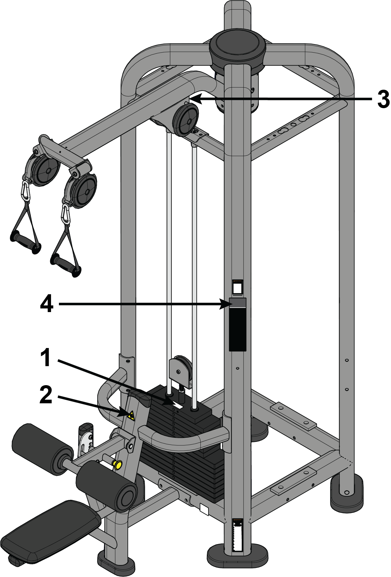
1.10.19: Power Pivot (PP-PP)

1.10.20: Rope Pull - Power Pivot (PP-RP)

1.10.21: Rope Pull (PP-RPL)

1.10.22: Low Row (PP-RW)

1.10.23: Dual Handle Low Row (PP-RWD)

1.10.24: Stall Bars (PP-SB)

1.10.25: Storage Station (PP-SC)

1.10.26: Step (PP-STP)

1.10.27: Storage Connector (PP-SX)

1.10.28: Triceps Pushdown (PP-TP)

Chapter 2: Assembly
2.1: Install Weight Stacks
- 5 mm Allen wrench
- Retaining ring pliers
-
Torque wrench
Note: All screws must be torqued to 25-30 FT-LBS. (27.1-33.9Nm).


Weight Stack Table
| Product | Weight Stack | Weight Plates |
|---|---|---|
| Attached Cable Crossover (PP-ACO) | 2 x 190 lb./95 kg. stack |
10 lb./4.5 kg. plate (x12) 15 lb./6.8 kg. plate (x16) |
| Free Standing Cable Crossover (PP-ACOFS) | 2 x 190 lb./95 kg. stack |
10 lb./4.5 kg. plate (x12) 15 lb./6.8 kg. plate (x16) |
| Assist Dip Chin (PP-ADC) | 295 lb./147.5 kg. stack |
20 lb./9 kg. plate (x19) |
| Adjustable Cable Column (PP-AP) | 190 lb./91 kg. stack |
10 lb./4.5 kg. plate (x6) 15 lb./6.8 kg. plate (x8) |
| Adjustable Pulley 4:1 (PP-AP41) | 390 lb./195 kg. stack |
15 lb./6.8 kg. plate (x19) |
| Embedded Cable Crossover (PP-AXO) | 2 x 190 lb./91 kg. stack |
10 lb./4.5 kg. plate (x12) 15 lb./6.8 kg. plate (x16) |
| Dual Pulley High (PP-DPH) | 290 lb./145 kg. stack |
20 lb./9 kg. plate (x14) |
| Dual Pulley Low (PP-DPL) | 290 lb./145 kg. stack |
20 lb./9 kg. plate (x14) |
| Attached High Low Crossover (PP-FCO) | 2 x 190 lb./95 kg. stack |
10 lb./4.5 kg. plate (x12) 15 lb./6.8 kg. plate (x16) |
| Embedded High Low Crossover (PP-FXO) | 2 x 190 lb./91 kg. stack |
10 lb./4.5 kg. plate (x12) 15 lb./6.8 kg. plate (x16) |
| High Low (PP-HL) | 190 lb./91 kg. stack |
10 lb./4.5 kg. plate (x6) 15 lb./6.8 kg. plate (x8) |
| Lat Pull (PP-LP) | 260 lb./127 kg. stack |
15 lb./6.8 kg. plate (x6) 20 lb./9 kg. plate (x8) |
| Dual Lat Pull (PP-LPD) | 260 lb./127 kg. stack |
15 lb./6.8 kg. plate (x6) 20 lb./9 kg. plate (x8) |
| Row (PP-RW) | 260 lb./127 kg. stack |
15 lb./6.8 kg. plate (x6) 20 lb./9 kg. plate (x8) |
| Dual Row (PP-RWD) | 260 lb./127 kg. stack |
15 lb./6.8 kg. plate (x6) 20 lb./9 kg. plate (x8) |
| Triceps Pushdown (PP-TP) | 190 lb./95 kg. stack |
10 lb./4.5 kg. plate (x6) 15 lb./6.8 kg. plate (x8) |
2.2: Install Top Mount
The following procedure shows how to install the top mounts to the CORE for the
following products: PP-DPH and PP-DPL.
- 5 mm Allen wrench
- 7 mm Allen wrench
- 17 mm open-end wrench
- Retaining ring pliers
-
Torque wrench
Note: All screws must be torqued to 25-30 FT-LBS. (27.1-33.9Nm).


2.3: Install Top Mount
The following procedure shows how to install the top mounts to the CORE for the
following products: PP-AP, PP-AP41, PP-AXO, PP-ACOFS, PP-ACO, PP-ADC, PP-FCO, PP-FXO,
PP-HL,
PP-LP, PP-LPD, PP-RP, PP-RPL, PP-RWD, PP-RW, and PP-TP.
- 7 mm Allen wrench
- 17 mm open-end wrench
-
Torque wrench
Note: All screws must be torqued to 25-30 FT-LBS. (27.1-33.9Nm).

2.4: Install Lower Mount
The following procedure shows how to install the lower mounts to the CORE for the
following products: PP-DPH, PP-DPL, PP-RWD, PP-RPL, PP-RW, and PP-SB.

2.5: Install Lower Mount
The following procedure shows how to install the lower mounts to the CORE for the
following products: PP-HL, PP-FCO, PP-FXO.

2.6: Install Lower Mount
The following procedure shows how to install the lower mounts to the CORE for the
following products: PP-AP, PP-AP41, PP-AXO, PP-ACOFS, and PP-ACO.
- 7 mm Allen wrench (x2)
-
Torque wrench
Note: All screws must be torqued to 25-30 FT-LBS. (27.1-33.9Nm).


2.7: Install Lower Mount
The following procedure shows how to install the lower mounts to the CORE for the
following products: PP-ADC.
- Retaining ring pliers
- 5 mm Allen wrench
- 7 mm Allen wrench (x2)
-
Torque wrench
Note: All screws must be torqued to 25-30 FT-LBS. (27.1-33.9Nm).


2.8: Install Handle Accessory Rack
The following procedure shows how to install the Handle Accessory Rack (HAR) to the
CORE.

2.9: Install Blank Shroud
The following procedure shows how to install the BLNKSHRD to the CORE.
- 7 mm Allen wrench
-
Torque wrench
Note: All screws must be torqued to 25-30 FT-LBS. (27.1-33.9Nm).


2.10: Install Front Shroud
The following procedure shows how to install the optional front shrouds to the
CORE.
- 5 mm Allen wrench
- 7 mm Allen wrench
- Retaining ring pliers
-
Torque wrench
Note: All screws must be torqued to 25-30 FT-LBS. (27.1-33.9Nm).
- Repeat steps 7 and 8 for right shroud.


2.11: Cable Routing
2.11.1: Adjustable Cable Column (MJAP), Adjustable Pulley 4:1 (MJAP41), Attached Cable Crossover (MJACO), Embedded Cable Crossover (MJAXO)

2.11.2: Dip/Chin Assist (MJADC)

2.11.3: Dual Lat Pull (MJLPD)

2.11.4: Dual Pulley High (MJDPH)

2.11.5: Dual Pulley Low (MJDPL)

2.11.6: Dual Row (MJRWD)

2.11.7: High Low (PP-HL), Attached High Low Crossover (PP-FCO), Embedded High Low Crossover (PP-FXO)

2.11.8: Lat Pull (MJLP)

2.11.9: Row (MJRW)

2.11.10: Triceps Pushdown (MJTP)

Chapter 3: Cable Handling Guide
3.1: Cable Connections, Seating, and Installation
Cable connections with threaded cable ends are required to be installed and maintained following the specifications identified below. Failure to follow these specifications can lead to the dislocation of the threaded cable during use and can cause serious injury. Along with securing the threaded cable end and jam nut, it is important to check the entire unit and ensure that all hardware is securely fastened and not left loose upon completion of cable installation.
Warning: Use of non certified “techs” note: Service warranties may be void if a
non-Life
Fitness
-certified technician
performs service work. Replacement of any strength cables should be performed by a
Life
Fitness
certified technician.
CABLE COMPONENTS

| Item | Description | Qty. |
|---|---|---|
| 1 | Cable Assembly | 1 |
| 2 | Cable Hangtag | 1 |
| 3 | Jam Nut | 1 |
| 4 | Head Plate Assembly | 1 |
| 5 | Weight Plates | 12 |
| 6 | Weight Selector Pin Assembly | 1 |
- Jam nuts must be tightened toward the head plate assembly and frame anchor. Torque the jam nuts to 20-25 ft-lbs. (27.2 - 24.0 Nm).
- Cable Hangtags to be removed by customer only.
3.2: Cabling Procedure
3.2.1: Direct Terminal
Direct terminal is when the cable is terminated directly at the head plate
assembly.
- Thread cable into the head plate assembly at least to the jam nut. This will ensure the proper minimum thread engagement depth of 1/2 inch (12.7mm).
- Cycle the machine to ensure that it is in proper working order.
- Check the cable to ensure there is proper tension.
- Tighten jam nut to 20-25 ft-lbs. (27.2 - 34.0 Nm).

3.2.2: Remote Terminal
Remote terminal is when the cable is terminated away from the head plate assembly;
either at the frame, workarm, etc.
- Measure the threaded end of the pulley assembly and cable.
- Screw the jam nuts onto the end of the thread on the pulley assembly and cable.
- Thread the pulley assembly into the head plate assembly at least 1/2 inch (12.7mm).
- Thread the cable into the remote terminal.
- Measure the exposed threads to verify that the proper thread engagement, minimum 1/2 inch (12.7mm), is screwed into the terminations.
- Cycle the machine to ensure that it is in proper working order.
- Check the cable to ensure there is proper tension.
- Torque the jam nuts to 20-25 ft-lbs. (27.2 - 34.0 Nm).

3.3: Tensioning Cable
Cable should have enough tension so it stays
seated into the pulley but not so tight that it raises the head plate off the weight
plate below
it.
- If the head plate has lifted, loosen the jam nuts at the terminations and loosen the threaded plugs a half turn until the head plate comes to rest on the weight plate below. Check that the threaded plugs are engaged at least 1/2” (12.7mm) at each termination.
- Ensure that the weight stack selector pin can pin into each weight plate.
- Tighten jam nuts to 20-25 ft-lbs.


3.4: Strength Cable Wear Guide
Replace cable at first sign of any of the following:
FRACTURES:


TWISTING/BINDING:
| Inspect casing to ensure wire rope is not twisting within its casing. Any sign of the cable twisting should be replaced immediately. |

BULGING:
| Internal wire rope strands can break within and coil causing a bulge to appear. Cable should retain same outside diameter throughout. |

FRAYED/EXPOSED WIRE ROPE:
| Any exposed wire rope protruding through the casing or at either end. |

FLATTENED:
| Section of cable is compressed and will not retain its shape (outside diameter). |

PERMANENTLY BENT:
| Cable has ‘kink’ and prohibits cable from laying straight. Wire rope may be unraveling beneath casing and is compromised warranting replacement. |

ENDS SEPARATING:
| Watch for component end of cable to pull away from cable assembly - look for exposed wire rope. |

3.5: Insert Inspection
Inspect insert within the strain-relief cable end
assembly and replace if any sign of damage.
- Check around plastic insert and the plastic housing for any excessive wear or damage.
- Replace plastic insert if cracked, torn, separated, overly worn or damaged in any way.
- Using a 4mm hex wrench, remove screws from the housing/link and the damaged insert from cable assembly. Replace damaged insert, reassemble components and tighten to 8-10 in-lbs (0.9-1.1 Nm).


Chapter 4: Bolt to Floor Guide
4.1: Introduction
Life Fitness designs its products to be stable when used as designed. Because strength training is dynamic, we cannot predict how users will ultimately use the products in all circumstances. Therefore, Life Fitness recommends that strength training equipment be secured to a solid, level surface to stabilize and eliminate rocking or tipping over. For some equipment, securing the equipment to the floor is REQUIRED.
| Unit | Recommended Bolt to Floor | Required Bolt to Floor |
|---|---|---|
| MJ with 3 or less weight stacks | X | |
| MJ with 4 weight stacks | X | |
| MJ with body weight training equipment, straps, ropes or chains | X | |
| MJ with no body weight training equipment, straps, ropes or chains | X |
Each new unit shipped comes with a multi-language hangtag stating the importance of bolting the unit down as a safety precaution.

It is the facility’s responsibility to adhere to local and regional building codes.
- Fasteners must have minimum embedment in concrete floor, not including screed, regardless of wood/tile/rubber over subfloor. (See Anchor Specifications for maximum subfloor thickness between unit and concrete to equipment foot must be made of flooring or other material (i.e. no air gaps)).
- DO NOT reuse fasteners. Static and Dynamic anchors are designed for one-time use only.
- Factor in equipment’s feet height when selecting fastener length.
- Factor in flooring thickness when selecting fastener length.
- It is also recommended to drill an additional 1/2” (12.7mm) of depth beyond the length of the fastener being used to ensure that debris does not block the entry of the anchor.
- Minimum concrete compressive strength: 3000psi (20 N/mm2).
4.2: Delivery and Installation Tips
All Anchors
- Fasteners must have minimum embedment in concrete floor, not including screed, regardless of wood/tile/rubber over sub-floor. (See Anchor Types for maximum sub-floor thickness between unit and concrete to equipment foot must be made of flooring or other material (i.e. no air gaps)).
- DO NOT reuse fasteners. Static and Dynamic anchors are designed for one-time use only.
- Factor in equipment’s feet height when selecting fastener length.
- Factor in flooring thickness when selecting fastener length.
- It is also recommended to drill an additional 1/2” (12.7 mm) of depth beyond the length of the fastener being used to ensure that debris does not block the entry of the anchor.
- Minimum concrete compressive strength: 3000 psi (20 N/mm2).
Anchoring
- All anchors must have a minimum embedment into concrete, regardless of wood/tile/rubber/screed over sub-floor.
- Dynamic anchors must have a minimum embedment depth in concrete to ensure maximum security and pull out force. See Anchor Types for embedment depth minimums.
Building Codes
It is the facility’s responsibility to adhere to local and regional building codes. Please verify with the customer to ensure that they are aware of this.
Carpeting
If bolted down to carpet flooring, be sure to use a box cutter knife to cut the carpet threads around each foot. This will help avoid the carpet threads from being wrapped around and pulled by the drill bit.
Competitor Product
The bolt down guidelines and procedures for Life Fitness products were determined by the company’s Engineering and Installation Development groups. These guidelines include which anchors to use and positioning of the anchors are required for Life Fitness product.
- Life Fitness does not have that level of specification or engineering input for competitive product.
- Life Fitness installation teams are not permitted to anchor competitor equipment.
Drilling
It is also recommended to drill an additional 1/2” (12.7 mm) of depth beyond the length of the fastener being used to ensure that debris does not block the entry of the anchor.
- This can be done by marking your drill bit with a piece of tape.
- While it is recommended that a vacuum be used to clean up debris, this will not account for all the debris that will settle at the bottom of the drilled hole.
4.3: Anchor Type - Static

4.4: Pullout Force
Life Fitness specifies Hilti™ static and dynamic anchors. According to the anchor manufacturer, the recommended design pullout force (in tension) for the specified anchors, when properly installed in cracked concrete, is provided in the side table. This table should be used for reference only; for additional and up-to-date information on the anchor capabilities or the design pullout force in other substrates, please consult Hilti directly at https://www.us.hilti.com.
| Dynamic Anchors | Design Resistance in Tension * |
|---|---|
| KB-TZ2 3/8" x 5” and HST3 10mm x 130mm | Greater than 2,000 lb (2.7kN) |
| Static Anchors | Design Resistance in Tension * |
|---|---|
| KH-EZ 1/4” | 830 lb (3.6 kN) |
| HUS-H 6mm | 3.3 kN (741lb) |
* Design strength extracted from the Hilti™ Anchor Fastening Technology Manual.
4.5: Tools Required
Warning: Adhere to manufacturer’s equipment warnings and guidelines. Follow
manufacturer’s instructions for proper usage.
- 1” L-shape SDS rotary hammer
- (Imperial anchors) 3/8" diameter carbide drill bit
- (Metric anchors) 10mm diameter carbide drill bit
- Extension cord
- Floor scanner / rebar detector (optional)
- Hammer (Dynamic anchors only)
- Rotary tool
- Safety glasses
- Tape measure
- Torque wrench
- Vacuum (for debris)
4.6: Anchor Procedure
- Place unit into position to be mounted and cycle unit to set its stance.
- Wearing protective glasses, drill down into flooring perpendicularly to the required depth, ensuring that the foot thickness of the unit is being accounted for; refer to Anchor Selection and Foot Dimensions.
- Clear out debris from hole.
- Insert anchor assembly. Use hammer to tap dynamic anchors flush against upright's base plate.
- Tighten to 30 foot-pounds for Imperial (45Nm for Metric), assuring there are at least 3 threads left exposed.
- If necessary, cut extra length from top of anchor with a rotary tool leaving proper concrete engagement, torque requirements and at least 3 exposed threads.
- Check anchors weekly and re-tighten to 30 Foot-Pounds for Imperial (45Nm for Metric) if needed. Failure to do so may jeopardize anchor effectiveness.


